To the surprise of absolutely nobody, the day I finally got my PipBoy 3000 Mk.V it was in pieces within an hour of me opening the box, so, maybe I can save everyone else the risk and satisfy some curiosity by describing what I found and a bit more information about how it works.
Dissasembly
Disassembly of the PipBoy 3000 was fairly straightfoward, the soft cuff parts pop straight out and then the plastic backing from behind it also just pops out. At this stage I opened the battery panel and took out the LiPo battery and set it aside. After that there are just 4 screws and the whole diecast from section comes away, being careful to not let it fall and pull on the cables!
The Pip-Boy FM FM Radio upgrade module was an optional addon by by The Wand Company to their Pip-Boy 2000 Mk VI. I bought mine quite a few years ago now for £30 GBP but I’ve since seen them go for almost 10 times that on eBay which has kind of put me off hacking on mine given the scarcity of them.
That said, I’ve always been curious about the four exposed pads in a hole on one end—could I power it from them? Could I use the amplifier inside to play my own audio? Recently, I spoke with Richard at The Wand Company about the exposed pads on the FM Radio upgrade. He shared a picture showing how the modules are positioned for production testing, where I assume pogo pins make contact with the pads for automation of testing. This reignited my interest in hacking the module, so I took the bold step of cracking it open to uncover its secrets.

Initial Disclaimer
So I was in two minds about whether to write this entry or not because I didn’t want to cause any harm or upset to a company I admire so much, so I reached out to Chris the CEO of The Wand Company who put me in touch with one of the engineers over there, Richard, and they have given me their blessing to write about the upcoming Pip-Boy 3000 Mk V.
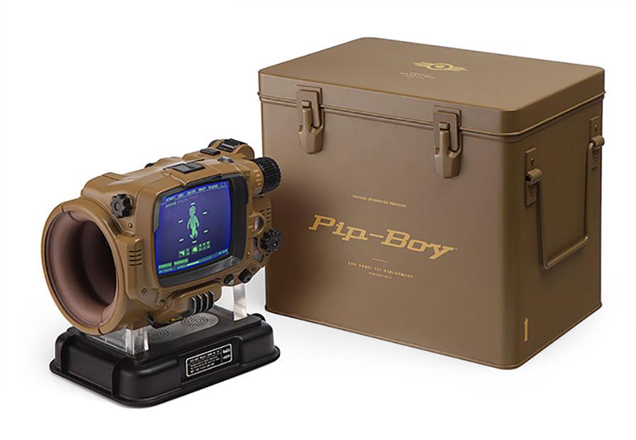
I recently acquired one of the rare, albeit flawed, Fallout 4 Deluxe Bluetooth Edition Pip-Boy 3000’s that were originally supplied by ThinkGeek and as I understand it were limited to 5000 units worldwide. Seemingly these units were flawed from day 1 and lots of people had issues with them failing, the one I acquired was one of these defective units, but I took it on board with the mind that one way or another I’d make something of it.
Having good hardware is only good if you can interface with it, this past phase of the construction has been trying to work out the best way to interact with my software using the PCB I created previously.
Architecture
To better understand the approach it’s worth first talking about the physicality of how this all connects together so we know where to start when it comes to writing code.
The board is based around an MCP23017 GPIO expander connected via I2C, all the buttons and rotary encoder are on bank A of this chip. In my case this is then connected to a Pi Zero 2 W via the I2C breakout on the back of the HyperPixel display, this adds a little bit of added complexity as the I2C on the HyperPixel display as it turns out is I2C over GPIO, but more on that later.