So far I feel like I’ve focussed a lot on the electronics of this project but one of the key elements that will sell this project as a real life Fallout 4 terminal is the physical presence of the thing. Getting this absolutely accurate has kind of been my key focus since day 0 of this project. I’ve talked a lot about the feel of the thing and the physical form it takes is of course one of the most important elements.
Computer Aided Design
Usually when designing a case for a computer, especially back in the era of real dumb terminals, I feel like the designers would have started from the inside out when designing, I feel like you’d take the things you know you have constraints on like the actual cathode tube etc. and then design the case to fit. In this case I feel like I did this whole process in reverse.
This is not my first time building CAD models from game models but this time there are definitely additional constraints and considerations to take into account. The design started out by taking the game model and importing it into CAD software, as this is aiming to be a complete replica I want to be at the least proportionally accurate. As I discussed previously in Bringing new life to an old CRT the first thing we need to establish was scale, in that last post you can actually see by that point I’d already done a lot of this process when choosing the appropriate display.
With the scale set I then imported front, rear, side and top projection images that I’d taken as screenshots in NifSkope, this helps when adding additional detail that may not be in the actual mesh and is part of the texture or normal maps.

At this point I worked from the outside in, first getting the basic shape of the case carved out by following the lines from the game mesh, then refining, adding detail, cutting it up. Rinse and repeat for a few weeks, because A) I’m a perfectionist and B) I’m not actually great with CAD.

Make it Real
At this point I realise that replicating the model is one thing, but I need to make this thing real, which as it turns out is a whole other thing. I will admit at this point initially I got a little stuck, I’m quite used to thrashing something out in CAD, sending it to my 3D printer and calling it done, but here I need to mount a CRT inside of it, along with various other PCB’s, transformers, some of which is of course hot and high voltage. So I reached out to Zapwizard, someone I know has experience in product design and also building Fallout prop replicas.
Metalwork
After some words of wisdom from the Zapwizard, we came to the conclusion that mounting CRT’s into custom enclosures is a path fairly well trodden in the world of arcade cabinets so I spent some time digging around various forums, it seems a lot of those enclosures are fairly simple plywood type boxes, which isn’t really the vibe I wanted but it gave me some inspiration.
Ultimately I need to support the CRT and associated PCB, and I also need to provide something for the main case to fasten to to provide some rigidity. The main front panel for the case also didn’t really suit 3D printing, the optimal solution would be a curved metal sheet, and after looking into how I might achieve that I realised that it’s actually incredibly simple, and relatively cheap now to get sheets of metal laser cut, which is incredible.
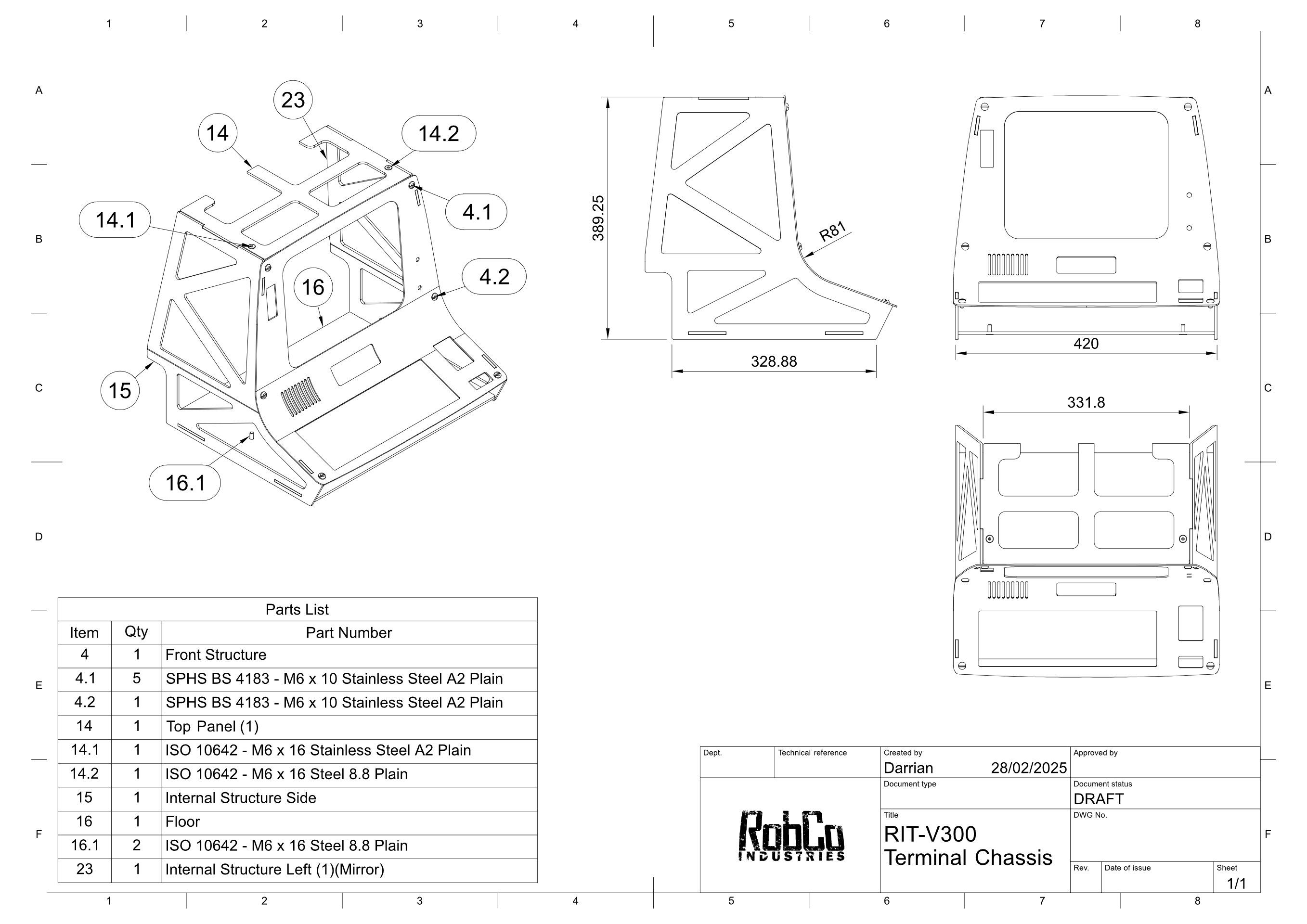
Given this discovery I decided I would design an all metal chassis to fit inside the external casing, and knowing it could be laser cut, I kind of went to town on it and spent some time making sure I got it right. The cover image at the top of this page is the result of that process.
The completed designs were sent off to LaserBoost and the fully shipped cost ended up at around $300. This is kind of higher than it needed to be but I kind of went overboard, everything was cut out of 4mm 5754 aluminium and vibration finished which was probably unnecessary. I also opted to have some of the bends added in for me to save some stress.
Mounting the CRT
There’s a number of ways I could approach mounting the CRT but my main concern was that I needed some kind of adjustments, because I was not at all confident in getting all of the elements lined up. I figured the easiest way to achieve this was to add two vertical 20x20 aluminium extrusions, the kind peoeple tend to use for DIY CNC routers and 3D printers, then mount things to that. This would also make mounting PCB’s and other parts much easier down the line.
Assembly
Once the metalwork came in from the laser cutters, I took it to a local welding certified in welding aluminium and had them fix everything together, at which point I realised how incredibly over engineered this whole project is, this thing is absolutely rock solid and absolutely did not need 4mm aluminium, but hey, it’s post apocalypse ready.
The aluminium extrusions are tapped at each end and then bolted from the top and bottom. Mounts designed to wrap around the extrusions and support the CRT are printed out of ABS and bolted onto the extrusions with slot bolts.


Conclusion
This part is getting pretty long so I’ll leave it here for now and I’ll follow up with another post talking about the process of fabricating the exterior casing and taking this frame into something that looks more like the final result.