It’s been a little while since the last entry, I took some time to learn Espruino better and contribute to some of the tooling to make hacking on these devices easier for everyone, but now we’re back and ready to try something new.
In the last entry I’d leveraged the exposed UART test pads to add a GPS receiver, mostly because I had the GPS laying around and it felt like a cool way to demonstrate the art of the possible, but the ultimate goal originally was to add bluetooth. I got a fair way down the road of programming an ESP32 that was piggybacked to the STM32 and sent data packets to Espruino, during this process I was looking for some example code and snippets from the Espruino repos and stumbled upon a module for the ESP8266 which was doing something fairly similar, but piggybacking an ESP8266 over UART for WiFi, very interesting! So I ordered a couple to see what fun could be had.
The Plan
In the previous experiment I’d already made use of the UART test points for GPS, so how hard could it be? I’d need to connect the ESP8266 up to power and the UART, load the ESP8266WiFi module onto the Pip-Boy, and that’s all, right?
“They say no plan survives first contact with implementation. I’d have to agree.”
- Andy Weir, The Martian
ESP8266
As expected, the connectivity here is pretty much the same as we did for the GPS previously, since then though I have decided to add a JST connector with both 3.3V and 5V rails so that in future when I chop and change things I can just plug up whatever I need without needing to take the device apart and solder things to the main board.

For now I’m using an Adafruit HUZZAH ESP8266 board and I’ve stuck it in the battery compartment (this poor thing hasn’t had a battery in it for months anyway). I do also have smaller variants of the chip so if I ever decide to make this a permanent feature then I’ll fit the whole package inside the main chassis rather than it hanging out in the battery bay, but for now this is the easiest way to prove a concept.

It’s worth noting that the ESP8266 requires more than 3.3V, in this case I’ve connected it to the 5V test pad which works great except the 5V rail comes from the USB connection, meaning there’s no 5V when the device is running on battery power. (Yes, I appreciate that this kind of defeats the idea of WiFi, we’re still attached to a wire)
Firmware
The Adafruit HUZZAH that I’m using came pre-loaded with NodeMCU Lua, which as it turns out is no use for our use case. The Espruino library that interacts with this chip expects it to be running firmware that takes AT commands, but they helpfully list some of the supported firmware versions in the documentation over at https://www.espruino.com/ESP8266#firmware-versions.
I went down a bit of a rabbit hole here trying to build the “latest” firmware from that page, but it seems it fell out of support in 2019, I then found a fork that was being maintained but the build tooling for that required Python 2 (who is using Python2 in 2025), so I gave up on that option, went back to the list of versions and grabbed the pre-build of version 1.3.0.0. I ended up flashing it using an FT232 and esptool.py to flash the binary like so:
esptool.py -p /dev/ttyUSB0 write_flash 0 ESP8266_AT1.3.0.0-512k.bin
Initial Testing
So the correct firmware is loaded, the wiring is done, that’s basically it right? Wrong. The first issue I came up against was an issue I encountered previously when using these UART pins and that is that by default Serial3 has the REPL attached, so any messages being sent my the ESP will be interpreted as commands and the LCD will spam with ReferenceError messages, so we’ll need to fix that before we can do anything.
Luckily the fix is really simple, previously in Hacking the PipBoy 3000 Mk V Bootloader we devised a method to run code at boot from the SD card, so we’re going to leverage that again here to run a command to disable REPL. The boot scripts on the SD card are executed in alphanumeric order so to make sure our fix runs as early as possible we create a file named USER_BOOT/10_repl.js with the contents:
E.setConsole("USB", { force: true });
This will force the REPL console to be on the USB connection only, no matter what, and that’s totally fine for what we need. Now when we reboot the device it will leave Serial3 free for our own use.
Required Modules
We also previously added external modules to the SD card so the plan here was to do the same thing again, since then however I’ve realised that I didn’t need to use Modules.addCached(...) to add the modules, Espruino will actually load modules from the SD card as standard, they just need to be in a directory named node_modules and have no file extension.
The main module we need is ESP8266WiFi which is downloaded an added to the SD card as node_modules/ESP8266WiFi. In my naiveté I now fired up a console, loaded the module and hoped I could simply connect to some WiFi and call it a day; but here comes the next issue, I’m also missing a couple of extra modules that are called by the ESP8266WiFi module, AT and NetworkJS. No problem, I thought, I’ll just download those and also add them to the SD card, I found the AT module no problem and went hunting for NetworkJS but could not find it anywhere. Eventually I located it though, and it turns out it’s native code that’s included in the firmware builds for Espruino boards that require it, and of course the Pip-Boy doesn’t need any of that stuff, why would it.
Building Custom Firmware
So it seems like I’m going to have to build custom firmware. It’s worth noting at this point that this is the first real use case I’ve come across that’s necessitated building custom firmware, I’ve had a lot of people ask me about modifying the firmware to add functionality and in 99% of cases most things can be modified just by running your own functions at boot time like we did in Hacking the PipBoy 3000 Mk V Bootloader and overriding functions and classes.
Before modifying any of the firmware I wanted to prove that I could build the standard firmware from source, flash it to the Pip-Boy and have everything function as normal, only once I knew the process was sound did I start making any modifications so any errors from here out I would know were caused by my modifications.
git clone https://github.com/Espruino/Espruino # Clone the Espruino source
cd Espruino
source scripts/provision.sh PIPBOY # Provision script will gather up some of the required STM32 libs etc.
make clean # Not necessarily needed first run, just good habit
RELEASE=1 BOARD=PIPBOY make # Creates a release for the PIPBOY board
Once running the above, the latest version of the firmware for the Pip-Boy is built, and in my case that now exists at bin/espruino_2v26.4_pipboy.bin.
Flashing Device Firmware
WARNING! The Pip-Boy is a pretty forgiving device and most things are “un-brickable” but this next step can take a bit more coming back from if you break something and don’t know exactly what you’re doing.
There’s a few options here for getting firmware onto the STM32, initially I was going to used the ST-Link that I’d bought for FM Radio Upgrade Reverse Engineering (Part 2) but then I discovered that you can also use DFU to flash firmware over USB, which is way more convenient, and even more convenient The Wand Company have provided us a page to do it from (thank you!) https://www.thewandcompany.com/pip-boy/dfu/
The aforementioned site has instructions but essentially you need to get the Pip-Boy to enter DFU mode, which is done by holding the hidden reset button, the flashlight button and the power button simultaneously and then releasing the reset button.
NOTE. On Linux I needed to do a few extra steps here to allow Chromium based browsers access to the DFU device, what I ended up doing that worked the most reliably was to take the udev rules from the STM32CubeProgrammer install, these were under ‘Drivers/udev’

At this stage I flashed what would be a fairly vanilla firmware that I built myself just to be sure the Pip-Boy booted okay, and to my delight it did, and at this stage it’s actually running a newer build of Espruino than the officially supplied firmware by The Wand Company, which incidentally appears to include a few Pip-Boy specific fixes, which is a nice bonus.
Customising the Firmware
So the main thing we need to add is network, so I took a look at some of the other Espruino board definitions that do support networking eg. https://github.com/espruino/Espruino/blob/RELEASE_2V26/boards/ESPRUINOWIFI.py#L34 and figured I just needed to add NET to the list of libraries, build again, job done. Not so simple as it turns out. When you build Espruino for a target board, it checks if the resulting binary size will fit within the defined bounds of the target device flash, and enabling NET made it too big. I did try to just flash it anyway and see what happened, but that definitely broke things, it didn’t boot as I kind of expected, so we need to shed something.
I had a bit of a dig around with various optimisations I might apply to the compilation but in the end I just wanted to have something working and wasn’t confident the JIT stuff was being used anywhere so I figured I’d just cut that library and see how much of a saving it made, and it turns out it was enough to fit. I ended up using the create_zip_board.sh script to do the builds, it did the clean and stuff for me so it was a bit more convenient, this was the resulting build command:
USE_JIT=0 USE_NET=1 scripts/create_zip_board.sh PIPBOY
As before this firmware was flashed using the DFU, and so far nothing bad has happened from removing JIT and the device boots just fine!
Testing
The first thing to check is that the native modules are now in the build as expected, and they are:
>process.env.MODULES.split(",")
=[
  "Flash",
  "Storage",
  "heatshrink",
  "fs",
  "net",
  "dgram",
  "http",
  "NetworkJS"
 ]
Now the network modules are in place and the other modules are on the SD card, we can try a full end to end test. This test will configure the UART connection, setup the ESP8266 library and then attempt to list all WiFi access points that the chip can see:
Serial3.setup(115200);
var wifi = require("ESP8266WiFi").connect(Serial3, (err) => {
  wifi.getAPs(console.log);
});
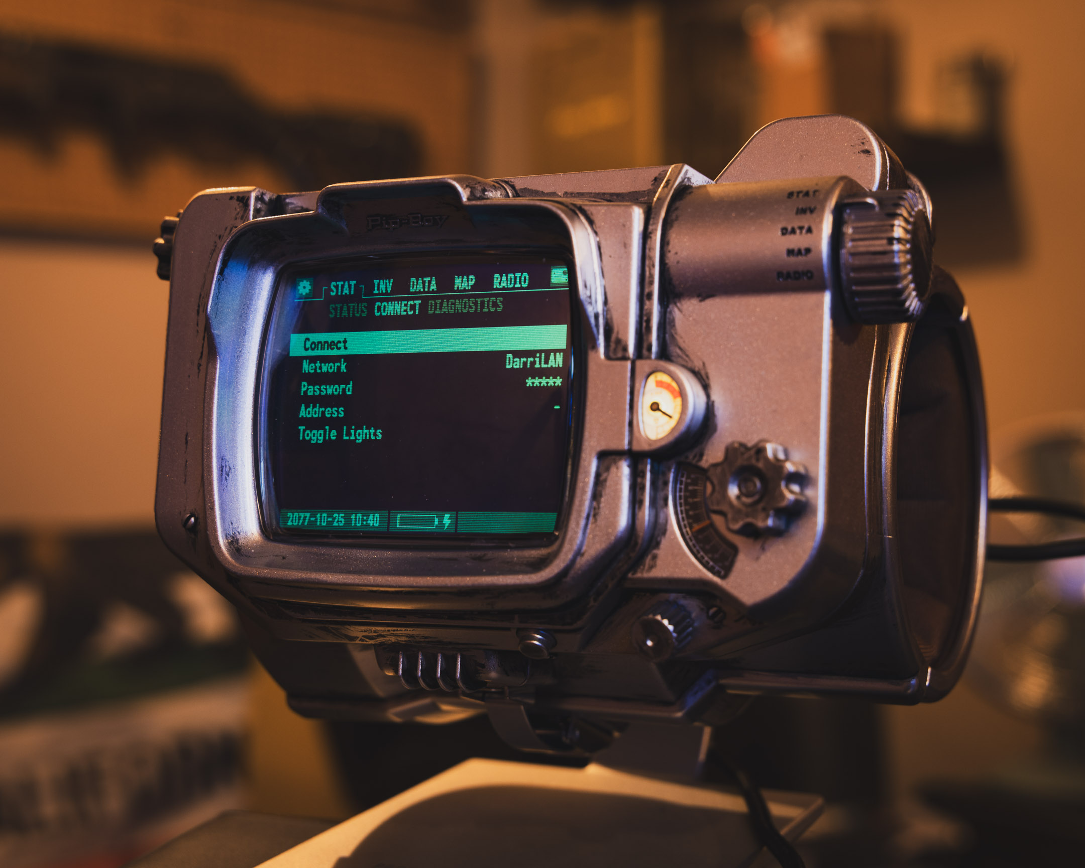
Interface Integration
Now that I have the basics in place, there’s just some polish to add to the implementation. I decided that the logical thing to do was to replace the CONNECT submenu with a new menu feature that had some of the WiFi connect functions, for simplicity I’ll load things like the WiFi pass key from the default settings.json that’s already used for system settings. The following script, like earlier, is run at boot time so I created it as USER_BOOT/20_wifi.js:
// Configure UART connection
Serial3.setup(115200);

// Extend the base 'Pip' global object with the new WiFi connection
Pip.wifi = require("ESP8266WiFi").connect(Serial3, (err) => {
  if (err) throw err;
});

// Keep a handle on IP address and connection state
Pip.ipAddress = null;
Pip.wifiConnected = false;

// Connection function that uses SSID and key from settings file to connect
Pip.wifiConnect = () => {
  submenuBlank(`Connecting to ${settings.wifi.ssid}...`)();
  Pip.wifi.connect(settings.wifi.ssid, settings.wifi.key, (err) => {
    if (err) throw err;
    Pip.wifiConnected = true;
    Pip.wifi.getIP((err, addr) => {
      if (err) throw err;
      submenuBlank(`Connected!\n${addr}`)();
      setTimeout(() => submenuWifi(), 3000);
      Pip.ipAddress = addr;
    });
  });
};

// New menu component, currently doesn't have modify functionality
const submenuWifi = () => {
  const m = {
    Connect: () => {
      Pip.wifiConnect();
    },
    Network: { value: settings.wifi.ssid || "-", onchange: () => {} },
    Password: { value: "*****", onchange: () => {} },
    Address: { value: Pip.ipAddress || "-", onchange: () => {} },
  };
  E.showMenu(m);
};

// Override the default `CONNECT` submenu with our new one
global.submenuWifi = submenuWifi;
(function () {
  if (MODEINFO) MODEINFO[1].submenu.CONNECT = submenuWifi;
})();
What Now?
Having connectivity opens up a lot of doors, there are definitely some limitations with the hardware etc. so fetching large amounts of data or having many sockets open is a no go (there appears to be a socket limit of 5 connections). So as a quick proof of concept I opted to use a basic HTTP webhook to my Home Assistant server to an automation that allows me to trigger whatever, in this case to toggle on/off a lightbulb.